3 Phase Pwm Inverter Circuit Diagram
Three phase inverter Inverter arduino circuits diagrams which Single phase half bridge inverter explained
Three-phase PWM inverters with a R-L load. | Download Scientific Diagram
Three phase inverter: it's basics and circuit diagram Three phase inverter circuit Three-level single phase inverter circuit
Make this 1kva (1000 watts) pure sine wave inverter circuit
Three-phase voltage source pwm inverter the circuit model of a typicalIc tl494 pwm modified sine wave inverter circuit Interlocking gate drivers for improving the robustness of three-phaseInverter phase circuit diagram principle.
Inverter phase circuit diagram motor three wiring make generator pwm homemade circuits schematic projects electronic solar single power simple explainedInverter pwm ic circuit sine wave tl494 modified functions executing pinout above looking many Three-phase pwm inverters with a r-l load.1, three phase inverter circuit.

Phase three gate inverter inverters isolated drivers ti industrial vfd robustness interlocking improving schematic 3phase figure technical
Inverter phase diagram three dc ac voltage wiring output current electronics tutorial ratings switches schema block dataPwm inverters Inverter phase circuit thyristor diode conduction degreeInverter pwm transistor six switches switch.
Three phase inverter circuit diagram – diy electronics projects3 phase inverter wiring diagram Inverter circuit sine wave pure diagram 1kva 1000 watts watt make circuits power dc eng pdf homemade using schematics kva.


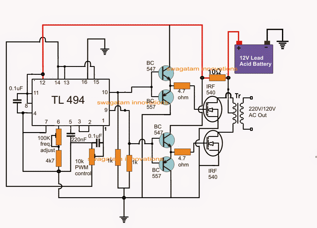
IC TL494 PWM Modified Sine Wave Inverter Circuit

Three Phase Inverter Circuit | Circuit Diagram Centre
Three-phase PWM inverters with a R-L load. | Download Scientific Diagram

Three Phase Inverter: It's Basics And Circuit Diagram - Quick Learn

Three Phase Inverter Circuit Diagram – DIY Electronics Projects

Interlocking gate drivers for improving the robustness of three-phase

Make This 1KVA (1000 watts) Pure Sine Wave Inverter Circuit

Three-level single phase inverter circuit | Download Scientific Diagram

Single Phase Half Bridge Inverter Explained - Electrical Concepts

3 Phase Inverter Wiring Diagram - Wiring Diagram