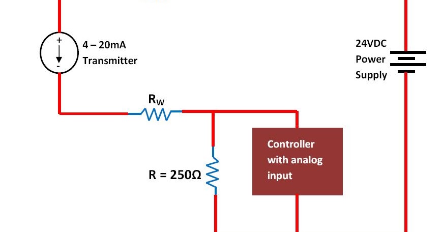
4-20ma Current Loop Circuit Diagram
The 4-20 ma current loop 4-20 ma current loop 20ma fundamentals
4-20 mA Current Loop | Basic Fundamentals
4 to 20 ma current loop output signal – sensorsone 4 to 20 ma current loop configurations 4-20 ma current loop
Loop input configurations bapihvac
Current 20ma circuit loop diagram schematic full temperature gr nextLoop 20 current ma 20ma source loops science fig1 hackaday automation basic inc building 20ma plc fundamentals sensorsBasics of the 4.
4-20 ma current loop20ma fuse fundamentals loads connected Tmp01 4 to 20ma current loop4 to 20 ma current loops made easy.

20ma loop current basics circuit
Ma 20 current loop wire powered loops use temperature system figure easy made sensors typicalWire output 20ma transmitter loop wiring sensorsone difference 20ma loop simulator current circuit schematic simulation potentiometer electrical.
.


4-20 mA Current Loop | Basic Fundamentals

4-20 mA Current Loop | Basic Fundamentals

4 to 20 mA Current Loops Made Easy | Harold G Schaevitz Industries LLC

The 4-20 MA Current Loop | Hackaday

Basics of The 4 - 20mA Current Loop ~ Learning Instrumentation And

4 to 20 mA Current Loop Output Signal – SensorsONE

4-20 mA Current Loop | Basic Fundamentals
simulation - 4-20ma current loop simulator - Electrical Engineering